Latest Products



Contact Us
- The Fourth Floor, A-A3 Zone, Aviation Business Area, DongLi Distrct, Tianjin, China.
- >salesmanager@coilwinding machinechina.com
- +8613072088960


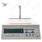
Voltage Transformer Field Tester
Bill error test range: 6KV/100V, 6KV/ √3, 20kV/100V, 20kV/√3, 35kV/100V, 35kV/√3, 66kV/√3, 110kV/√3, 220kV/√3
Queue Supports testing up to three groups of secondary windings, namely 1A1n, 2A2n, and 3A3n, each with a maximum secondary load of 200VA.
Can store more than 1000 sets of test data.
Costing the device weighs about 22kg.
Lent accuracy level: 0.05
Description
1. Large screen of Voltage Transformer Field Tester with backlight touch screen LCD: resolution 1024×600 points, all measurement data and relevant operation tips are displayed in Chinese.
2. Transformer: the internal output high voltage end of primary A terminal of the instrument is connected to the primary A terminal of the transformer. The short-term maximum output voltage is 2kV during the working process, which is led out by the special high voltage insulation wire.
3. Transformer: the primary N terminal is connected to the primary N terminal of the transformer, led out by the special high voltage insulation wire, the voltage transformer must be reliably grounded before measurement!
4. PT secondary winding: the 1A1N instrument adopts four-wire connection, the yellow terminal of the test line is connected to the 1A end of the secondary transformer, and the black terminal of the test line is connected to the 1N end of the secondary transformer.
5. PT secondary winding: the green terminal of the 2A2N test line is connected to the 2A end of the secondary transformer, and the black terminal of the test line is connected to the 2N end of the secondary transformer.
6. PT secondary winding: the red terminal of the 3A3N test line is connected to the 3A end of the secondary transformer, and the black terminal of the test line is connected to the 3N end of the secondary transformer.
7. Ac power socket with switch: AC 220V±10%, frequency 50±0.5Hz.
8. Voltage Transformer Field Tester grounding terminal: Before testing, ensure that the terminal is reliably connected to the ground. Must be grounded!
9. Printer: Used to print error data
11. High voltage output switch: used to cut off the high voltage output, in the test process should be switched on.
11. USB interface: the data stored in the Voltage Transformer Field Tester can be downloaded to the USB disk, and the data in the USB disk can be imported into the instrument.
12. RJ45 network port: upgrade interface of the instrument software.
13. Traditional test terminals: TERMINALS A and X are the working voltage input terminals, and terminals K and D are the differential voltage or differential current input terminals.
Hot Tags: voltage transformer field tester, China, suppliers, manufacturers, factory, price, made in China
CHAPTER 4 USE METHOD
一、use preparation
l Measuring instruments automatically has to be live, so operators have to comply with safety regulations.
l Check the insulation of each measuring line using a multimeter before connecting to a network, to prevent accidents to the grid and equipment caused by a short circuit on the measuring line.
l A connection is made by connecting a terminal on the instrument panel first and then the line to be tested.
l Do not touch the high voltage TERMINALS A and N during the test.
l Automatically press the high voltage output switch to shut down the high voltage output if an exception is found during a test.
l The grounding terminal must be grounded reliably.
l Anyway, after a beta test, make sure you shut down the power line anyway!
●To restart the system by switching off the power for three seconds, restart the system again to ensure that all hardware circuits are powered down.
二、Operation method
After startup, the instrument interface is as follows:
Click "Error Measurement" to enter the measurement interface:
1、Error measurement interface
1) Factory number
Click here, a soft keyboard pops up, you can modify the factory number of this data.
2) model
All models stored in the system are displayed in the drop-down list. In System Settings, you can add, modify, or delete models.
3) Test type
PT by default.
4) Power factor
All power factors stored in the system are displayed in the drop-down list box. You can add, modify, or delete a power factor in System Settings.
5) frequency
The default frequency 50 hz.
6) Terminal mark
Click here to display the name of the test winding. If blank is selected, all information of the winding end will be screened out.
7) Whether to measure
Click here to select whether to test the winding error data.
8) Rated primary voltage
All the rated primary voltages stored in the system are displayed in the drop-down list box. You can add, modify, or delete the rated primary voltages in System Settings.
9) Rated secondary voltage
Automatically generated according to the rated primary voltage, no need to fill.
10) Accuracy level
All accuracy levels stored in the system are displayed in the drop-down list. You can add, modify, or delete accuracy levels in System Settings.
11) Rated load
All the rated loads stored in the system are displayed in the drop-down list. You can add, modify, or delete the rated loads in System Settings.
12) Lower limit load
The lower limit of the internal storage capacity is displayed in the drop-down list box. You can add, modify, or delete the lower limit in System Settings.
13) Whether the primary terminal is connected
You can select Yes or No. If yes is selected, the primary terminal is connected throughout the test without secondary cables. When selecting "No" (when the transformer ratio under test is greater than or equal to 35/0.1kV, the default value is "No"), click "Start Measurement", the following picture will pop up on the interface to confirm whether the primary terminal is disconnected. If the primary terminal is disconnected, click "Yes"; otherwise, click "No".
15) Start measuring
Set the parameters of the transformer, select the serial number of the secondary winding to test the error, click start to test the error, and the instrument will check the wiring first.
If "Yes" is selected because the primary terminal is not disconnected due to misoperation, the device will automatically check whether the primary terminal is connected before measurement. At this time, the following figure will pop up indicating that the primary terminal is not disconnected, and then disconnect the primary terminal according to the prompt.
You Might Also Like