Latest Products



Contact Us
- The Fourth Floor, A-A3 Zone, Aviation Business Area, DongLi Distrct, Tianjin, China.
- >salesmanager@coilwinding machinechina.com
- +8613072088960


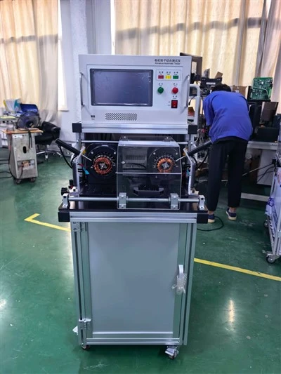

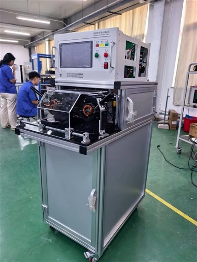


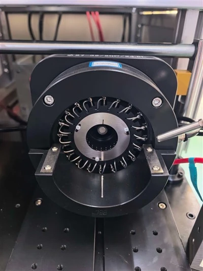

Automatic Armature Commutator Testing Equipment
Model:GWYD‑90B
Test items:Withstand voltage, insulation resistance, surge test, welding resistance, bar-to-bar resistance, cross-bar resistance
Application:Armature rotors
Armature bars:5–72 bars (optional)
Description
GWYD-90B Armature Rotor Comprehensive Tester
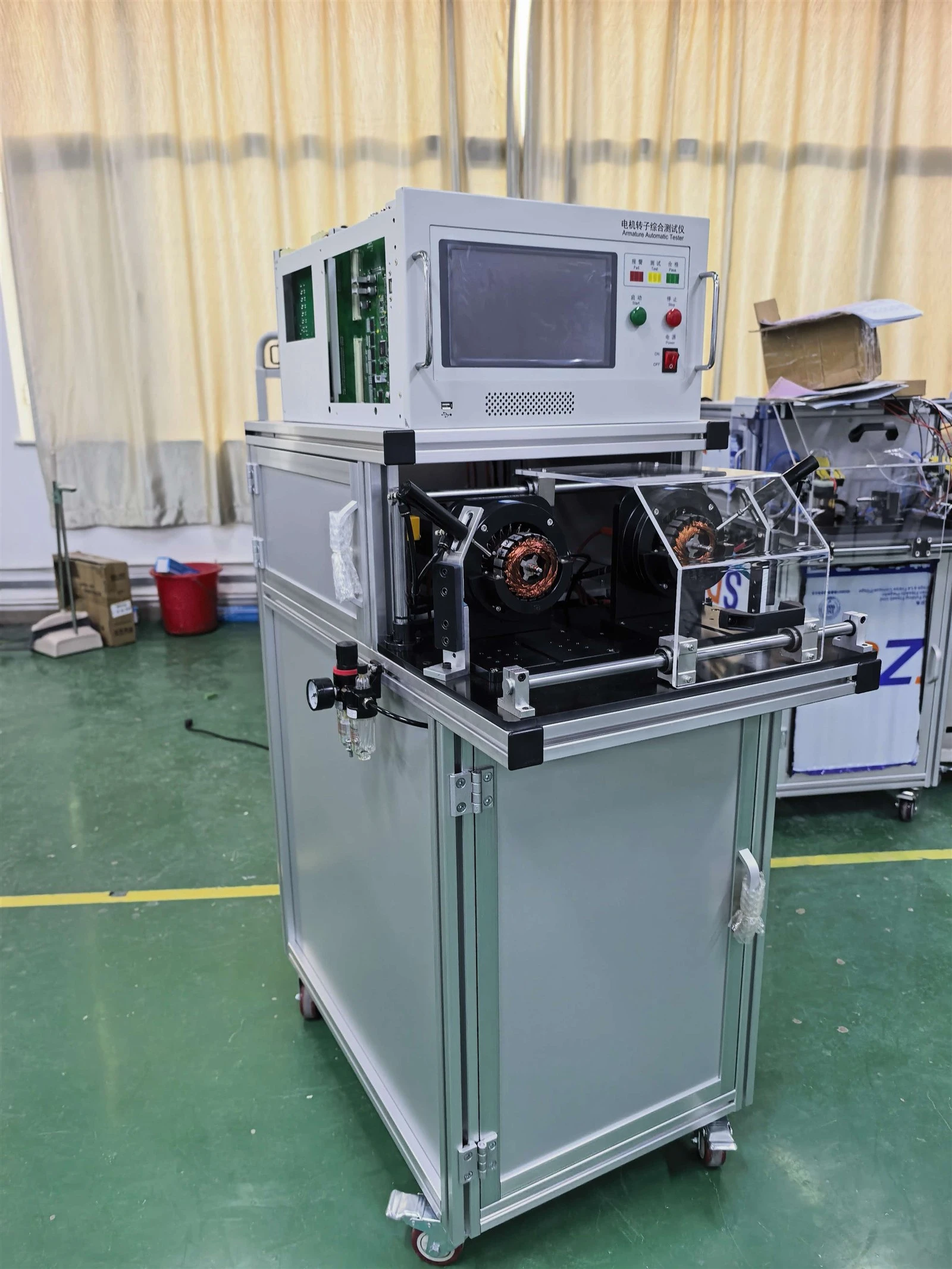
Functional Features:
- All-in-one testing: Automatically completes all electrical performance tests in one ultra-fast operation, including insulation resistance, power-frequency withstand voltage, bar-to-bar resistance, cross-bar resistance, welding resistance, and surge withstand voltage.
- Optional bar-to-bar resistance test: Automatically identifies faults such as short circuit, open circuit, and out-of-limit resistance, and provides fault location information.
- Automatic process recognition: Automatically identifies single-fly / double-fly winding processes regardless of armature placement, and accurately sorts bars. Automatically tracks bar resistance differences to analyze slight variations in coil turns, magnet wire diameter, and winding tension.
- Unique surge withstand test: Supports optional bar-to-bar testing, adjustable impact times, and automatic multi-waveform comparison judgment.
- High speed & efficiency: Meets high-speed production takt. Testing time: approx. 3.5 seconds for 12-bar armatures, approx. 6 seconds for 24-bar armatures.
- Superior safety performance: Industry-leading test specifications.
- Optional functions: Dual insulation and multi-point power-frequency withstand voltage measurement.
- Automatic statistics: Counts total tested pieces, pass rate, and classifies defective products by fault type.
- Model copy: Supports fast copying of test conditions for different motor models among multiple testers via USB flash drive.
- Large memory: 400 test groups, storing settings and standard waveforms for 400 rotor models.
- Dual-station fixture: Equipped with a dedicated dual-station operating fixture for easy and safe operation; output channels are selectable.
- 10.2-inch touch screen: User-friendly operation.
- Strong anti-interference: Multiple anti-interference designs ensure high consistency, repeatability, and stability.
- Easy maintenance: Modular design for convenient function upgrades.

Technical Parameters
|
Item |
Specification |
|
Test items |
Withstand voltage, insulation resistance, surge test, welding resistance, bar-to-bar resistance, cross-bar resistance |
|
Application |
Armature rotors |
|
Armature bars |
5–72 bars (optional) |
|
Display |
10.2-inch true-color touch screen |
|
Alarm |
Audible and visual alarm (buzzer) |
|
Test station |
Cabinet type, dual station |
|
Test groups |
400 memory groups |
|
Key Technical Specifications: |
|
|
DC Resistance(Bar-to-bar & Cross-bar) |
Measuring range: 0.500 mΩ–500 Ω (auto-ranging, temperature compensated) Accuracy: ≤1 mΩ: ±(1.5% of reading +3 digits); >1 mΩ: ±(0.5% of reading +3 digits) |
|
Welding Resistance |
Measuring range: 0.001–100.0 mΩ Accuracy: ≤1 mΩ: ±(1% of reading +3 digits); >1 mΩ: ±(0.5% of reading +3 digits) |
|
Insulation Resistance |
Test voltage: DC 0.30–1.00 kV Voltage accuracy: ±(2% of reading +5 V) Measuring range: 0.5–2000 MΩ Accuracy: ≤100 MΩ: ±(3% of reading +0.3 M); >100 MΩ: ±(5% of reading +5 M) Test time: 0.0–999.9 s |
|
Power-Frequency Withstand Voltage |
Test voltage: AC 0.10–3.50 kV (dual insulation optional) Voltage accuracy: ±(2% of reading +5 V) Leakage current: 0.10–20 mA Accuracy: ±(2% of reading +5 digits) Current zero return: 0.00–3.00 mA Test time: 0.0–999.9 s |
|
Surge Withstand Voltage |
Peak voltage: 0.50–3.00 kV Accuracy: ±(5% of reading +10 V) Waveform comparison: Corona, area, differential product, phase Impact times: 1–20 times Sampling frequency: 50 MHz |

Operating Procedures
3.1 Pre-Calibration Preparation
3.1.1 Prepare the following tools and measuring instruments: Inter-bar resistance & current calibration tooling, welded resistance calibration tooling, standard resistors (0 mΩ, 1 mΩ, 10 mΩ, 100 mΩ, 1000 mΩ), Type BZ3 DC standard resistor, Type ZX119-2 adjustable high resistance box for megohmmeter calibration, 2 sets of FLUKE 45 multimeters, JDZ-10 high voltage transformer (Ratio: 10000:100), MD70 standard hipot tester, 40mA/100mA hipot resistor bank, oscilloscope and DP-50 voltage attenuator.
3.1.2 Adjust the temperature and humidity of the test room. Keep the ambient temperature at 20±10℃ and relative humidity ≤75%. Record temperature and humidity in the factory calibration record form.
3.2 Technical Requirements
3.2.1 Visual Inspection
3.2.1.1 Markings and characters on the tester housing shall be clear.
3.2.1.2 Power switches and start/stop buttons shall operate flexibly and reliably.
3.2.1.3 Power sockets, fuse holders and terminal blocks shall be firmly installed.
3.2.1.4 Front panel shall be flat without warping; all fixing screws shall be fully tightened with no missing parts.
3.2.2 Safety Specification Calibration
3.2.2.1 Calibration Items: Inter-bar resistance, welded resistance, insulation resistance, AC hi-pot, inter-turn hi-pot.
3.2.2.2 Calibration Parameters: Refer to enterprise standards.
3.2.2.3 Calibration Criteria: Refer to enterprise standards.
3.2.2.4 Calibration Method: Complete wiring as required.
After verifying the correct connection, perform safety specification tests.
3.2.2.5 Data Recording: Record all safety specification parameters and test results on the calibration record form of the tester under test.
3.2.2.6 Non-Conforming Handling: If the tester fails calibration, send it to the customer service department for maintenance, and re-calibrate after repair.
3.2.3 Performance Inspection
3.2.3.1 Display: LCD brightness shall be normal with no garbled characters.
3.2.3.2 Measurement Accuracy: The deviation between measured value and actual value shall not exceed the error range specified in the appendix.
3.3 Calibration Implementation
3.3.1 Visual Inspection
Check items one by one in accordance with Clause 3.2.1. The tester shall fully comply with all visual requirements.
3.3.1.1 Power On
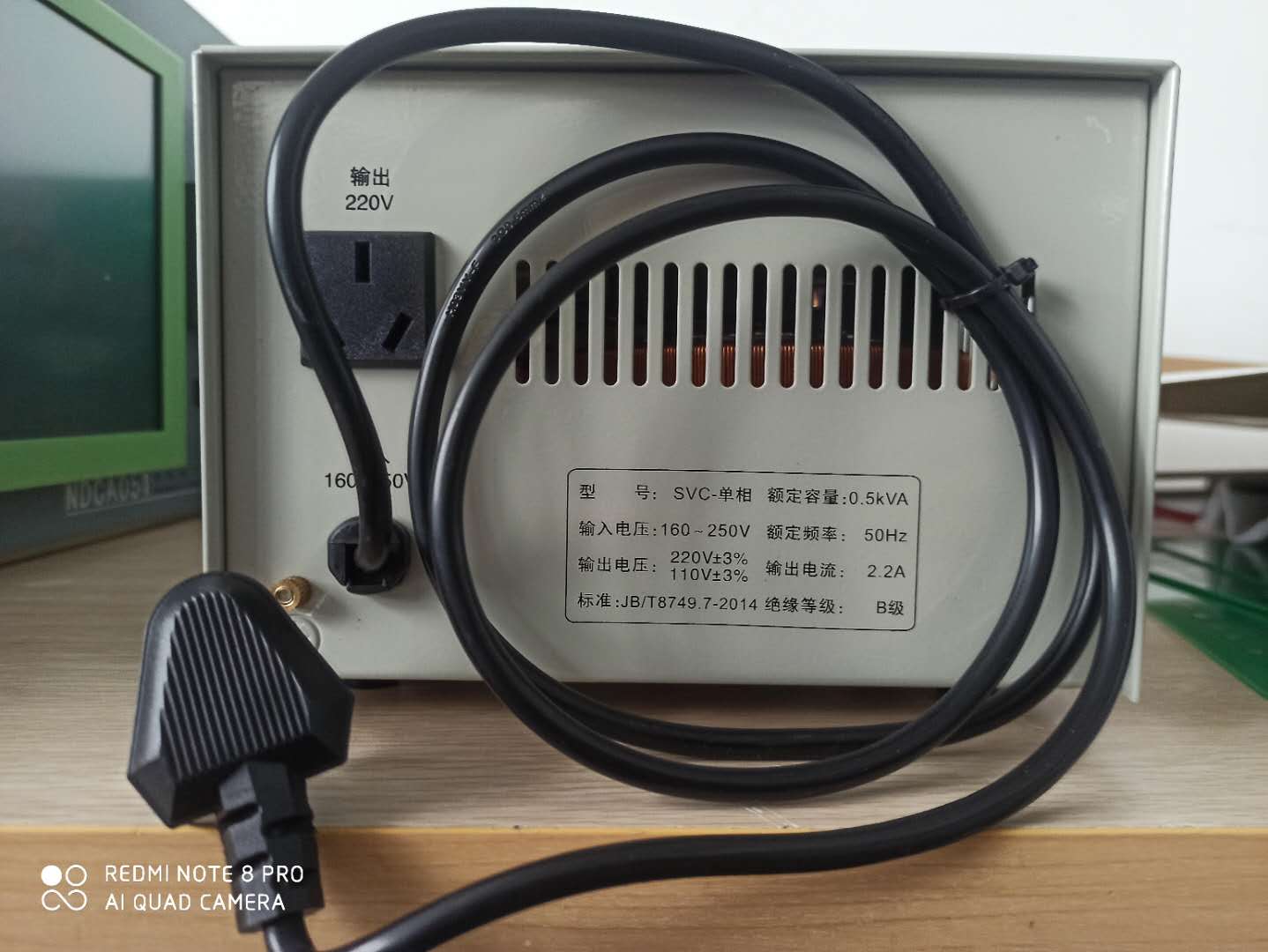
Connect the tooling to the GWYD-90B tester. Plug the regulated power supply into mains power, and connect the GWYD-90B tester to the 220V output terminal of the regulated power supply, then power on the device.
3.3.2 Performance Test
3.3.2.1 Display Check
Power on the tester and verify the LCD display meets the requirements in Clause 3.2.3.1.
3.3.2.1.1 Welded Rotor Tooling Test
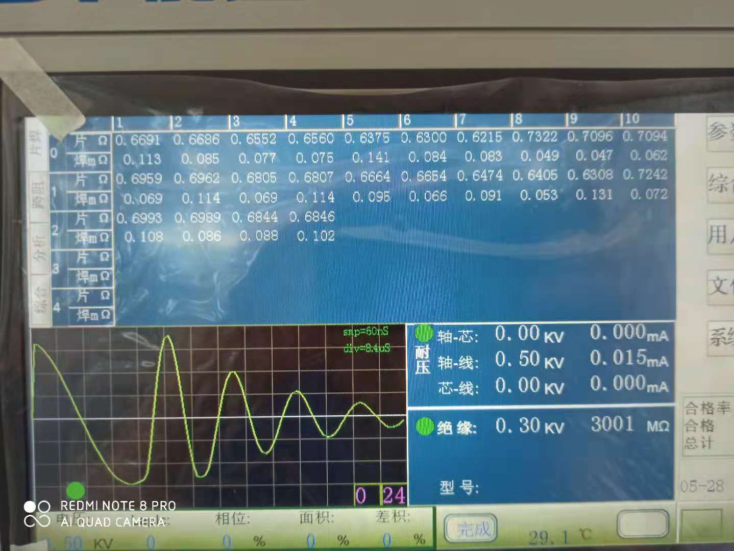
Before accuracy calibration, connect the welded rotor tooling to test inter-bar resistance and welded resistance. The test values shall be within a reasonable range without large deviations. It is prohibited to have three normal readings and three abnormally high readings for welded resistance.
3.3.2.2 Inter-Bar Resistance Calibration
3.3.2.2.1 Wiring
Connect all standard resistors as shown in Figure 1: Inter-Bar Resistance Wiring Diagram.

3.3.2.2.2 Calibration Steps
Calibration resistance points: 1 mΩ, 5 mΩ, 10 mΩ, 50 mΩ, 100 mΩ, 500 mΩ, 1 Ω, 5 Ω, 10 Ω, 50 Ω, 100 Ω, 500 Ω.
Switch to the Inter-bar, Welded & Cross Resistance parameter setting interface.
Set parameters: Winding direction & sequence judgment: Disabled; Armature segment number: 12; Test time: 0; Sample quantity: 1; Standard temperature: 25℃; Temperature drift: 0; Upper & lower limits of Inter-bar Resistance 1 & 2: 0; Inter-bar resistance dispersion rate: 0; Welded resistance: 0; Upper & lower limits of cross resistance: 0; Welded resistance gear: Fixed.
Set the upper limit of Inter-bar Resistance 1 sequentially to 1 mΩ, 10 mΩ, 100 mΩ, 1000 mΩ, 10 Ω, 100 Ω, 500 Ω.
Switch to the inter-bar resistance test page, start the test, and record readings for each resistance point in sequence.
3.3.2.3 Welded Resistance Calibration
3.3.2.3.1 Wiring: Connect the calibration tooling as shown in Figure 2: Welded Resistance Wiring Diagram.

3.3.2.3.2 Calibration Steps
Calibration resistance points: 1 mΩ, 5 mΩ, 10 mΩ, 50 mΩ, 100 mΩ.
Switch to the Inter-bar, Welded & Cross Resistance parameter setting interface.
Set parameters: Winding direction & sequence judgment: Disabled; Armature segment number: 12; Test time: 0; Sample quantity: 1; Standard temperature: 25℃; Temperature drift: 0; Upper & lower limits of Inter-bar Resistance 1 & 2: 0; Inter-bar resistance dispersion rate: 0; Welded resistance: 0; Upper & lower limits of cross resistance: 0; Welded resistance gear: Fixed.
Switch to the welded resistance test page, start the test, and record readings for each resistance point in sequence.
3.3.2.4 Insulation Resistance Calibration
3.3.2.4.1 Voltage Calibration (Wiring)
Connect the high-voltage terminal 1 to the positive terminal of the DC voltmeter, and terminal U1 to the negative terminal of the DC voltmeter (See Figure 3: Insulation Voltage Wiring Diagram).

3.3.2.4.2 Voltage Test
Switch to the Insulation Resistance parameter setting interface.
Set the test voltage sequentially to 0.3KV, 0.5KV, 1.0KV.
Switch to the insulation resistance test page, run the test, and record readings.
3.3.2.4.3 Resistance Calibration (Wiring)
Connect the high-voltage terminal 1 to the high-voltage end of the high-resistance box, and terminal U1 to the low-voltage end of the high-resistance box (See Figure 4: Insulation Resistance Wiring Diagram).

3.3.2.4.4 Resistance Calibration Steps
Calibration resistance points: 2 MΩ, 8 MΩ, 20 MΩ, 80 MΩ, 200 MΩ, 800 MΩ, 2000 MΩ.
Switch to the Insulation Resistance parameter setting interface.
Set the test voltage to 0.5KV and 1.0KV, respectively.
Switch to the insulation hipot test page, run the test, and record readings for each resistance point.
3.3.2.5 AC Hipot Calibration
3.3.2.5.1 Voltage Calibration (Wiring)
Connect high-voltage terminal 1 to the primary side of the high-voltage transformer, and terminal U1 to the other primary terminal. Connect the secondary side of the transformer to the AC voltmeter (See Figure 5: AC Hipot Voltage Calibration Wiring Diagram).

3.3.2.5.2 Voltage Test
Switch to the AC Hipot parameter setting interface.
Set test voltage sequentially to 0.5KV, 1.0KV, 2.0KV, 3.0KV, 5.0KV.
Switch to the AC hipot test page, run the test, and record readings.
3.3.2.5.3 Current Calibration (Wiring)
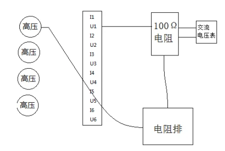
Connect the resistor bank and 100Ω resistor in series between high and low voltage terminals. Use an AC voltmeter to measure the voltage across the 100Ω resistor (See Figure 6: AC Hipot Current Measurement Wiring Diagram).
3.3.2.5.4 Current Test
Calibration current points: 0.2mA, 1.2mA, 1.8mA, 2.1mA, 8.0mA, 18.0mA.
Switch to the AC Hipot parameter setting interface and set the test voltage to 0.5KV.
Switch to the AC hipot test page, run the test, and record readings for each current point.
3.3.2.6 Inter-Turn Hipot Calibration
3.3.2.6.1 Wiring
Connect terminal I1 to the HV (High Voltage) port of the inter-turn tooling, and terminal U1 to the low-voltage port. Clip the oscilloscope cable to the Shield (L) port, and attach the probe to the Red & Blue (H) port (See Figure 7: Inter-Turn Voltage Measurement Wiring Diagram).

3.3.2.6.2 Voltage Test
Switch to the Inter-Turn Hipot parameter setting interface.
Set parameters: Impact times: 1; Impact interval: 1; Pass times: 1. Set test voltage sequentially to 0.5KV, 1.0KV, 2.0KV, 3.0KV.
Set DP-50 voltage attenuator to ×1000, oscilloscope attenuation to ×1000, time base to 10μs. Set trigger mode to rising-edge normal trigger, and measurement item to peak voltage. Capture complete and proper waveforms (avoid undersized waveforms).
Run the test on the inter-turn hipot standard sampling interface, and record peak voltage readings for each voltage level.
3.3.2.7 Sample Test
Connect the rotor tooling.
Switch to the parameter setting interface.
Set parameters correctly according to the specifications of the rotor sample.
Go back to the standby interface and run the comprehensive test. Check whether the test result is qualified and whether any alarms are triggered.
Intentionally set incorrect parameters against the rotor sample specifications.
Run the comprehensive test on the standby interface again, and verify that corresponding alarms are activated.
3.3.2.8 Additional Tests
3.3.2.8.1 Alarm Test: Upper limit alarm, over-range alarm, short circuit alarm, pass alarm, and fail alarm.
3.3.2.8.2 Safety Cover Test: Set startup mode to safety cover activation. Slide the safety cover and check if the tester starts normally.
3.3.2.8.3 RS232 Communication Function Test
3.3.2.8.4 Other Customized Functions: Inspect according to specific modification requirements.
3.4 Factory Default Setting
After passing all calibration items, initialize the tester and clear all custom settings.
Appendix: Table 1 Performance Specifications
|
Function |
Item |
Delivery Standard |
Internal Control Standard |
|
Inter-bar Resistance |
Test Method |
4-wire measurement |
- |
|
Test Range |
0.500 mΩ ~ 500 Ω |
- |
|
|
Measurement Accuracy |
≤1 mΩ: ±(1.5% of reading + 3 digits)≤500 Ω: ±(0.5% of reading + 3 digits) |
80% of delivery standard |
|
|
Temperature Compensation |
Available |
- |
|
|
Welded Resistance |
Test Method |
6-wire measurement |
- |
|
Minimum Segment Number |
5 segments |
- |
|
|
Test Range |
0.001 ~ 100.0 mΩ |
- |
|
|
Measurement Accuracy(0 Ω < Inter-bar Resistance < 10 Ω) |
≤1 mΩ: ±(1% of reading + 3 digits)≤100 mΩ: ±(0.5% of reading + 3 digits) |
80% of delivery standard |
|
|
Temperature Compensation |
Available |
- |
|
|
Ambient Temperature Measurement |
Temperature Sensor |
DS18b20 |
- |
|
Measurement Range |
-40.0°C ~ +120.0°C |
- |
|
|
Minimum Resolution |
0.1°C |
- |
|
|
Measurement Accuracy |
±0.5°C (0°C ~ +50°C) |
- |
|
|
Insulation Resistance |
DC Output Voltage Range |
0.30 ~ 1.00 KV |
- |
|
Voltage Resolution |
0.01 KV |
- |
|
|
Voltage Accuracy |
±(2% of reading + 5 V) |
80% of delivery standard |
|
|
Resistance Test Range |
0.5 ~ 2000 MΩ |
- |
|
|
Resistance Resolution |
0.1 MΩ |
- |
|
|
Resistance Accuracy |
≤100 MΩ: ±(3% of reading + 0.3 MΩ)>100 MΩ: ±(5% of reading + 5 MΩ) |
80% of delivery standard |
|
|
Test Time Range |
0.0 ~ 999.9 s |
- |
|
|
Time Resolution |
0.1 s |
- |
|
|
AC Hipot Test |
AC Output Voltage Range |
0.10 ~ 3.00 KV, 50 Hz |
- |
|
Voltage Resolution |
0.01 KV |
- |
|
|
Voltage Accuracy |
±(2% of reading + 5 V) |
80% of delivery standard |
|
|
Leakage Current Range |
0.10 ~ 20.00 mA |
- |
|
|
Current Resolution |
0.001 mA |
- |
|
|
Current Accuracy |
±(2% of reading + 5 digits) |
80% of delivery standard |
|
|
Test Time Range |
0.0 ~ 999.9 s |
- |
|
|
Time Resolution |
0.1 s |
- |
|
|
Inter-Turn Hipot |
Output Voltage Range |
0.30 ~ 3.00 KV |
- |
|
Voltage Step |
0.01 KV |
- |
|
|
Peak Voltage Accuracy |
±(5% of reading + 15 V) |
80% of delivery standard |
|
|
Max. Sampling Frequency |
50 MHz |
- |
|
|
Test Inductance Range |
>50 μH |
- |
Hot Tags: automatic armature commutator testing equipment, China, suppliers, manufacturers, factory, price, made in China
You Might Also Like