
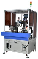
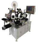
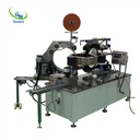
Latest Products


Contact Us
- The Fourth Floor, A-A3 Zone, Aviation Business Area, DongLi Distrct, Tianjin, China.
- >salesmanager@coilwinding machinechina.com
- +8613072088960


Turns Tester For Transformer Inductor
Magnetic coil turns tester is an equipment of good quality and low price, used to test all kinds of magnetic coil turns. Featuring strong functions, outstanding performance and easy operation, the equipment meets the needs of high-precision testing and productive spot high- speed testing.
Description
NAME: GW-9107A Turns tester for transformer Inductor
Specifications
Testing range | 0---20000 turns |
Testing precision | 0.1% |
Testing speed | twice/sec |
Testing frequency | 10kHz,2kHz,200Hz |
Coil dimensions | internal diameter>3mm, external diameter≤90mm |
Choice function | absolute error choice and percentage error choice |
Power supply Voltage | AC 220V±10% |
Power supply Frequency | 50Hz±5% |
Power supply Power | ≤30W |
Volume | Main equipment: 390*160*420mm Testing equipment: 185*150mm |
Weight | Main equipment: 5kg Testing equipment: 1kg |
1.1 Introduction
Magnetic coil turns tester is an equipment of good quality and low price, used to test all kinds of magnetic coil turns. Featuring strong functions, outstanding performance and easy operation, the equipment meets the needs of high-precision testing and productive spot high- speed testing.
1.2 Principle Sketch
1.3Technology Index
1.3.1 Testing range: 0---20000 turns
1.3.2 Testing precision: 0.1%
1.3.3 Testing speed: twice/sec
1.3.4 Testing frequency: 10kHz,2kHz,200Hz
1.3.5 Coil dimensions: internal diameter>3mm, external diameter≤90mm ( can be made to special measure )
1.3.6 Choice function: absolute error choice and percentage error choice
1.4 Operating Conditions
1.4.1 Condition temperature and humidity
The accuracy can be achieved when temperature is between 10℃and 30**, humidity≤80%RH.
The equipment can be operated when the temperature is between 0** and 40**, humidity ≤90%RH.
1.4.2 Power supply
Voltage: AC 220V±10%
Frequency: 50Hz±5%
Power: ≤30W
1.4.3 Volume
Main equipment: 390*160*420 ( width*height*depth )
Testing equipment: 185*150mm ( diameter*height )
1.4.4 Weight
Main equipment: 5kg
Testing equipment: 1kg
1.5 External Structure
1.5.1 Testing equipment
3 Illustration
Number | Name | Function Illustration |
1 | Socket | Connect with the main equipment with the five-wired electric cable to provide testing signal. |
2 | Auxiliary stick | During testing, turn the auxiliary stick into close contact with the main stick. |
3 | Awl support | Fix the coil to surround the main stick and reduce the error caused by the position of the coil. |
4 | Main stick | Put the coil around the main stick and contact the awl support horizontally to reduce the error. |
1.5.2 Illustration
序号 | Name | Function Illustration |
1 | Switch | “ON” to have the power supply and “OFF” to switch off. |
2 | Testing end | Provide four-end testing. HD,HS are connected to one end of the coil; LD,LS are connected to the other end of the coil. |
3 | Keyboard | To choose the functions. |
4 | Function instruction | To indicate the different functions. |
5 | Screen | The testing result and the function instructions show on the screen. |
1.5.3 Illustration
Number | Name | Function Illustration |
1 | Socket | Connect with the main equipment with the five-wired electric cable to provide testing signal.。 |
2 | Power supply socket | Connect with 24V,60Hz alternating current. |
Hot Tags: turns tester for transformer inductor, China, suppliers, manufacturers, factory, price, made in China
Chapter 2 Operation Instructions
The instrument resumes the last measurement state automatically when it is turned on. All the functions of the measurement show on the panel and can be got through the four buttons “∧”、“∨”、“ < ”、“ > ”. The indicator lamp of a function shines when pressing “ < ”、“ > ” to the function you need, then the parameters of the function can be chosen by pressing 上下 to where the indicator lamp shines.
Functions:
A. F---Frequency: 10kHz, 2kHz,200Hz
B. C---Choice: Off, Absolute error (Δ), Percentage error (Δ%)
C. S---Sound: Off, Qualified (Q), Unqualified (U)
D. P---Parameter: Read directly(D), Rectification A(R.A.), Rectification B (R.B.)
E. M---Measurement Range: Turns more than 1000 (M), Turns fewer than 500 (F)
F. W---Way: Continuous, Single
2.1 Measurement
2.1.1Connect the testing equipment with the main equipment using five-wired electric
cable, and connect the clip-wires with the main equipment.
2.1.2 Plug the wire into the jack at the back of the instrument, and press POWER.
2.1.3 Press RESET to the measurement state at any time.
2.1.4 Choose the testing method by pressing “∧”、“∨”、“ < ”、“ > ”. (See details in 2.2)
2.1.5 Put the magnetic-ring coil around the main stick; turn the auxiliary stick into close contact with the main stick.
2.1.6 Connect the two end lines of the tested coil using the clip-wires.
2.1.7 The number of the coil turns shows on the screen.
2.2 Function Instructions
2.2.1 Testing Frequency
Three frequencies (10kHz, 2kHz, 200Hz) can be chosen. To get best testing
effect, suitable frequency should be chosen according to the kind of coil.
2.2.2 Parameter
Generally, the testing result of coil of high magnetic permeability is stable and
accurate. While the result might be inaccurate when the coil is of low magnetic
permeability or the coil winding is unequal, but the result can be rectified by the
following ways:
a. Read Directly
The turns number can be read directly.
b. Rectification A
This rectification can be used when the result is inaccurate and the coil has one winding. 40 coil turns storage cells are provided, each one can store the rectifications of a show value. And the Choice function is done according to the show value. (See details in 2.2.4.1)
c. Rectification B
This rectification can be used when the result is inaccurate and the coil has two windings. 20 coil turns storage cells are provided, each one can store the rectifications of the show values of the two windings. And the Choice function is done according to one of the standard value. (See details in 2.2.4.2)
The storage cells and the rectifications won’t be lost because of power break.
2.2.2.1 Rectification A
a. Press “ < ” or “ > ” to where the Parameter lamp shines.
b. Press “∧” or “∨” to where Rectification A shines.
c. Press SET-UP, “-a-xx” shows ( xx is flash, the number is between 00 and 39.).
d. Press “∧” or“∨” to set the number of the storage cell, then press SET-UP.
e. Repeat 2.2.2.1.d and 2.2.2.1.e to rectify the show value to the coil turns
number. Note that the rectification can not exceed +/-20% of the directly-read
number, otherwise ERROR shows.
f. Press SET-UP or START, the rectified number will be stored in the xx storage
cell and coil turns testing can start.
2.2.2.2 Rectification B
a. Press “ < ” or “ > ” to where the Parameter lamp shines.
b. Press “∧” or “∨” to where Rectification B shines.
c. Press SET-UP, “-b-xx” shows ( xx is flash, the number is between 00 and 19.).
d. Press “∧” or “∨” to set the number of the storage cell, then press SET-UP.
“-B-1” shows and the rectification of the first winding starts.
e. Repeat 2.2.2.1.d and 2.2.2.1.e to rectify the show value to the coil turns
number.
f. Press SET-UP, “-B-2” shows. The rectification of the second winding starts.
g. Connect the two end lines of the second winding using the clip-wires.
h. Repeat 2.2.2.1.d and 2.2.2.1.e to rectify the show value to the coil turns
number.
i. Press SET-UP or START, the rectified number will be stored in the xx storage
cell and coil turns testing can start.
Note: When Rectification B is used, the turns of two windings should differ
from each other. The rectification can not exceed +/-40% of the directly-read
number, otherwise ERROR shows.
2.2.3 Measurement Range
Generally, parameter M is chosen when the coil turns are more than 1000, and
F is chosen when the turns are fewer than 500. Either of them can be chosen
when the turns are between 500 and 1000.
2.2.4 Way
a. Continuous Measurement way
The instrument continuously measure, calculate and show the coil turns.
The latter measurement goes immediately after the former one.
b. Single Measurement Way
The latter measurement goes only after START is pressed after the former one
is done.
You Might Also Like


