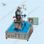
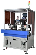
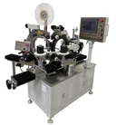
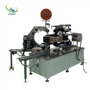
Latest Products


Contact Us
- The Fourth Floor, A-A3 Zone, Aviation Business Area, DongLi Distrct, Tianjin, China.
- >salesmanager@coilwinding machinechina.com
- +8613072088960


GW 901A Coil Turns Measuring
This instrument is used for measuring the turns of various types of coils, such as motor windings, generator windings, transformers and transformer coils, relay coils, TV HV/LV convertors, auto ignition coils. Thanks to the precision sensor and microcomputer circuit produced with the patent technologies, this instrument features the advantages such as high precision, powerful function, low influence on the coil shapes and geometric dimensions, reliable and easy operation. Accuracy values of the measured coils can be easily read from the instrument without any adjustment and calibration to the instrument, which greatly improve the measuring efficiency.
Description
GW 901A Coil Turns Measuring
I. Overview
This instrument is used for measuring the turns of various types of coils, such as motor windings, generator windings, transformers and transformer coils, relay coils, TV HV/LV convertors, auto ignition coils.
Thanks to the precision sensor and microcomputer circuit produced with the patent technologies, this instrument features the advantages such as high precision, powerful function, low influence on the coil shapes and geometric dimensions, reliable and easy operation. Accuracy values of the measured coils can be easily read from the instrument without any adjustment and calibration to the instrument, which greatly improve the measuring efficiency.
II. Schematic Diagram

III. Main Technical Index
3.1 Measurement Accuracy: 0~300 turns ±0 turn
300~500 turns ±1 turn
500~2000 turns ±0.2%
2000~6000 turns ±0.5%
3.2 Measurement Range: 0~60000 turns
3.3 Geometric Dimensions of Coil to be Measured: Inner diameter > 4mm (special requirement ≤ 4mm)
Height ≤ 110mm (special specification > 110mm)
Outer diameter ≤ 110mm (special specification > 100mm)
3.4 Power Supply: AC220V±10%, 50Hz
3.5 Working Conditions: Ambient Temperature: +5°C ~ 35°C;
Relative Humidity: <85%
3.6 Weight: Approx. 7Kg
3.7 Overall Dimensions: 370 x 220 x 110 (mm)
3.8 Specification of Test Bar: ¯10、¯6、¯4
Note: Coils less than 2000 turns shall be measured at a fast speed and coils greater than 5000 turns shall be measured at a slow speed.
The measure accuracy for coils with special specification will be determined with users through consultation.
Hot Tags: gw 901a coil turns measuring, China, suppliers, manufacturers, factory, price, made in China
IV. Operation
4.1 Connect the Measuring Sensor
Connect the two measuring leads (red & black) respectively into the wiring holes on the rear side of the instrument. Connect the 4-core and 5-core sockets on the rear side of the main unit respectively with those on the sensor with the 4-core and 5-core wires built in the instrument.
4.2 Connect the Power Supply
Plug the power cord into the power supply socket on the rear side of the instrument and turn on the power switch. Warn up the instrument for 5min after the display is activated.
4.3 Turn the horizontal tumbler on the measuring sensor counter-clockwise to a desired position (not exceeding 45°) and put the coil to be measured onto the test bar of the sensor. Then reset the horizontal tumbler on the sensor.
4.4 Measurement
4.4.1 Connect the two terminal wires of the coil to be measured respectively with the red and black measuring leads and make sure the electrical connections are in good condition in order to minimize the effects of contact resistance.
4.4.2 Phase Display
When the instrument is working in a continuous measuring mode after being switched on, the number of the coil turns will be displayed on the screen. The mark “-” which may or may not be shown in front of the value indicates the two different winding direction of the coil.
4.4.3 “Measuring Speed” Key
When the “FAST” lamp is on, the instrument is working in a fast measuring mode (at a measuring speed of approx. 0.35s/time). Press the “Measuring Speed” key once again, the “FAST” lamp is off, and the instrument is working in a slow measuring mode (at a measuring speed of approx. 0.84s/time)
4.4.4 “SOULD SELECTION” Key
Three pilot lamps (“PHASE”, “OPEN CIRCUIT” and “MUTE”) on the top right of the instrument are used to indicate three sound modes The instrument can be switched among these three sound modes by pressing the “SOUND SELECTION” key. If the “PHASE” lamp is on, the alarm will sound only when the phase mark “-” is displayed on the screen or there is an electric contact error. If the “OPEN CIRCUIT” lamp is on, the alarm will sound only when the coil to be measured has an open circuit or is disconnected or there is an electric contact error. If the “MUTE” lamp is on, the alarm will sound only when there is an electric contact error
4.5 If the measured coil has an open circuit, or is disconnected or the coil resistance is greater than 50KΩ, the instrument will display “E┌┌ □┌”.
4.6 When there is an electric contact between the coil and the test bar of the sensor, the “ELECTRIC CONTACT” pilot lamp on the instrument will illuminate.
4.7 If the instrument is exposed to serious electromagnetic interference and can not work normally, make sure to eliminate the interference source before performing any measurement.
V. Precautions
5.1 Avoid any large electromagnetic interference around the instrument to avoid affecting the accuracy of the instrument.
5.2 An open circuit inside the coil to be measured may affect the measurement accuracy.
5.3 While putting the measured coil onto the test bar, make sure the lower end of the windings is set against the test table and the test bar is in the middle of the coil, in order not to affect the accuracy of the instrument
5.4 Make sure there is a good contact between the coil lead wires and the wire clips.
5.5 Prevent the test sensor from any collision and rotate it within approx. 45°avoid any damage.
5.6 The test sensing assembly has been calibrated by using a special instrument and shall not be dismounted or modified without authorization, otherwise it will affect the measurement accuracy.
VI. Complete set of the Instrument
6.1 GW-901A Coil Turns Measuring Instrument 1 set
6.2 Power Cord 1 pc
6.3 Measuring Wire 1 set
6.4 Four & Five-core Connecting Wire 1 set
6.5 User Instructions 1 set
6.6 Quality Certificate 1 set
VII. Storage and Warranty Period
7.1 The product shall be stored with its original package in an indoor environment with an ambient temperature of 0~40°C and a relative humidity of not greater than 85%, and free of any hazardous substances in the air which content is enough to cause corrosion.
7.2 The manufacturer shall provide a warranty service free of charge for any and all quality defects or malfunctions found in the product and its accessories within 18 months from the date of delivery if the user has fully observed the requirements on storage, installation and operation stipulated in the User Instructions provided by the manufacturer and the product seal is intact.
You Might Also Like